Functional Architecture. What Is It and Why Every System Engineer Should Care.
Systems engineers frequently ask me how to identify specific functions and corresponding systems and then specify how they work together. This is a frustration for them because, although there are a few papers and tutorials on this topic, there is nothing in the SysML specification about this. SysML also does not specify how you should do functional architecture, functional allocation, or functional decomposition. Yet it is one of the most important, if not the most important, goals of the system engineer. In this blog, I will go through the different approaches and evaluate the pluses and the minuses of each method. Then I will propose a new approach.
Functional architecture describes “an architectural model that identifies system functions and their interactions. It defines how the functions will operate together to perform the system mission(s). Generally, more than one architecture can satisfy the requirements, Berton Manning for the Department of Defense (DoD). Systems engineers should begin with this concept first and foremost. Architecture and design are closely intertwined. The former focuses on the abstract, and the latter focuses on the concrete. However, both are integral to the system. “The object or goal of engineering is a design. . . the engineer has no direct way to arrive at the design such as by a set of formulas that can simply be evaluated. Instead, he or she must create (or invent) and plan. . . although engineering applies science, it is an art rather than a science “. . . from the SMS System Engineering Handbook.
Form Follows Function
American architect Louis Sullivan coined the phrase “form follows function” in 1896, though it is somewhat misleading. He stated, “It is the pervading law of all things organic and inorganic, of all things physical and metaphysical, of all things human and all things superhuman, of all true manifestations of the head, of the heart, of the soul, that the life is recognizable in its expression, that form ever follows function. This is the law.” Paraphrasing Sullivan here, the form of the building should come from its function, not from classical architecture.
Form Follows Function . . . Follows Purpose
However, today’s systems have a better fit for this phrase in that form follows function, which in turn follows purpose. As a systems engineer, you should be thinking in terms of functions first, rather than structure, where function is describing what the system is to perform. What functions do you want the system to do? Not doing so will immediately put you into a restricted boundary of building what you have always built. You will be doing it in the way you have always done it before.
For example, instead of saying, “I want to build an engine” you should be saying, “I want to take chemical energy and convert it into mechanical energy.” This is the service or a capability that you want the system to perform. Once you define a capability, start looking at what functions you need to get this done. Does the customer want power generation, do they want to haul a certain amount of weight, or do they want something to turn? Then, and only then, can you consider form.
If you don’t identify your functions first, then you won’t be innovating, you will merely be re-creating. In order to discuss functional architectures, we must consider both functional decomposition and functional allocation. Essentially, what we need to do is decompose functions into sub-functions in order to have the appropriate function/form relationship.
Let’s Discuss Functional Decomposition First
Consider a washing machine. What is it supposed to do? Of course, its function is to clean clothes, but perhaps it has other functions. For instance, we can ask how it cleans clothes. It has a warm and a cold setting. These are also functions. After decomposing functions into sub-functions, you can then allocate them to the appropriate system or subsystem. A sub-function’s purpose reveals the system-level function. So, how do I do that? The next step is to identify the forms. Maybe I need a wash drum, or perhaps an agitator. Defining what functionality you need to achieve allows you the freedom to figure out which forms could possibly perform it.
You take that function and specify that “clean” allocates to these particular forms: an agitator, a drum, water, water level, water temperature, soap, and viscosity. Then, all of this other stuff has to happen to get to the end result. Keep in mind, you will need to determine the systems to do each subset of things. Each has a different meaning. For example, if you ask, “what does an agitator do, and which things have functions?” The answer is, it scrubs or agitates clothes. Therefore, I need to scrub clothes in order to get clothes clean. This is an example of decomposing “clean clothes” into; I need to [scrub clothes] in order to get them [clean.] Then I need an agitator, so that these two become allocated to each other. So I take my function of “scrub clothes” and apply it to “agitator.”
Functional Decomposition in SysML
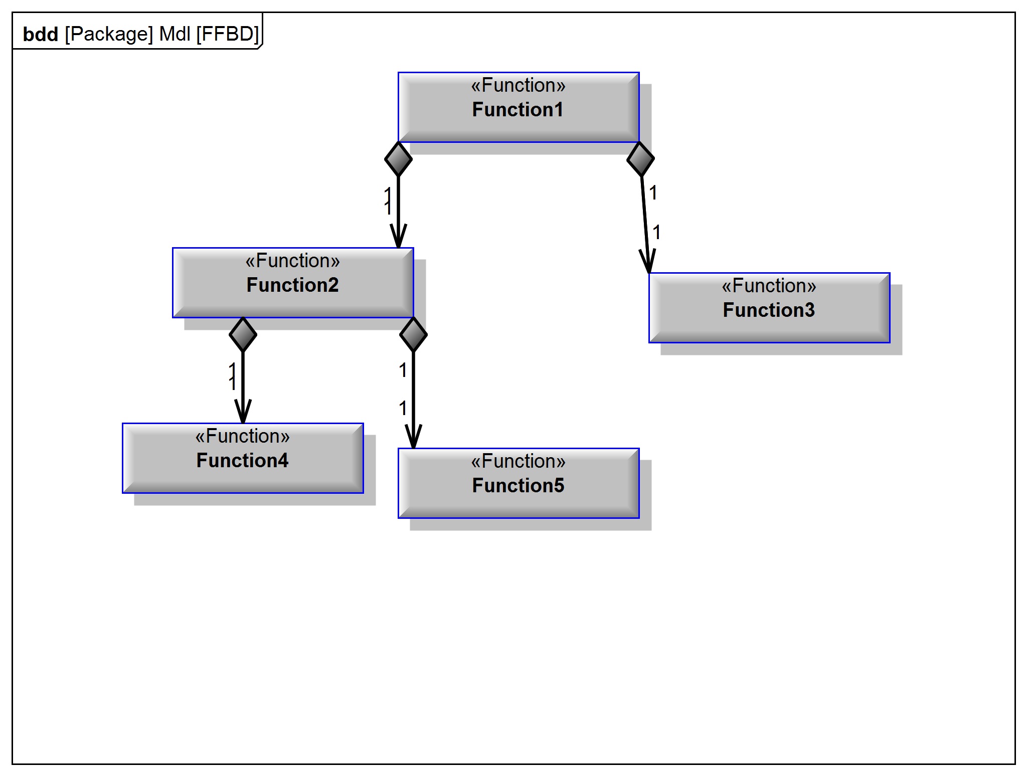
What you can do with functional decomposition, in terms of SysML, is quickly document on any diagram what functions your system is performing. You can even break down what sub-functions they do. This is the decomposing part. This is done on a Block Definition Diagram (BDD). Based on the research of others outlined below, you can use a myriad of techniques from Activities to Blocks to define “Functions.” I am proposing a new technique called Functional Flows, using a combination of Block <<Functional Blocks>> and using those blocks in information flow on a Internal Block Diagram (IBD) as an Item Flow <<Functional Flow>>. After determining the decomposition, you can start thinking about the structure. Then you can allocate those function to the appropriate form. At this point you will have [these functions] and [this system] and how they work together, and can generate an Allocation Matrix to this relationship.
Different Approaches to Functional Architecture in SysML
Functions as Activities
Sanford Friedenthal, along with Alan Moore and Rick Steiner describe functions as activities (OMG SysML Tutorial). This approach allows for activity hierarchies, solving the need to create Functional Flow Block Diagrams (FFBD). Activities are allocated to the system structural elements via the <<allocation>> relationship. The major downside to this approach is the inability to see the big picture. You will most likely dive into diagram after diagram after diagram. Or, you will need to make a mock activity to house another set of call behaviors, which are not the ones calling the original functions. Confused? I would think so.
In my opinion, this methodology is simply misconstrued and awkward. And you have consider, do I want the allocation between the types of the system or the parts of the system . . . between the call behaviors or the functions directly? Every modeling environment requires specific configuration to make the allocation work. Thus the need for a consultant to help with how the tools behave.
Functions as Operations
Michael Vinarcik elaborated this approach in 2015 (Vinarcik, 2015). This method makes use of call operations from SysML activity diagrams by creating one requiring an operation contained within a system <<block>>. Using this technique automatically dictates functions of the system will be a direct tie to the system structure. The name/modeling item is a one-to-one coupling. This method requires no additional scripting, and you can complete function allocation without using the <<allocation>> relationship.
With this method, you don’t have to allocate anything, which is of course a good thing. However, if you wanted to see them all in one diagram, how would you do this? That would mean all of the operations would have to exist in one system structure, and you wouldn’t want that again. How do you create different viewpoints without going deep into the decomposition of decomposition, ad infinitum? So this approach has big picture limitations as well.
Functions as Blocks
Jesko Lamm and Tim Weilkiens propose a method to have activities represented as a <<functional element>>. The <<functional element>> directly creates a corresponding <<functional block>> which is a <<block>> having <<functions>> that are operations. Functional decomposition is done using activity diagrams and the <<functional elements>> (Lamm & Weilkiens, 2010). This hybrid approach goes a little bit further in that blocks allow you to do other things like state based behavior. But there is still the issue of not being able to see everything in one diagram. Therefore, the end result amounts to duplication and the challenge of keeping a one-to-coupling across activities and blocks.
MBSE Solutions’ Proposed Technique – Functions as Item Flow or Functional Flows
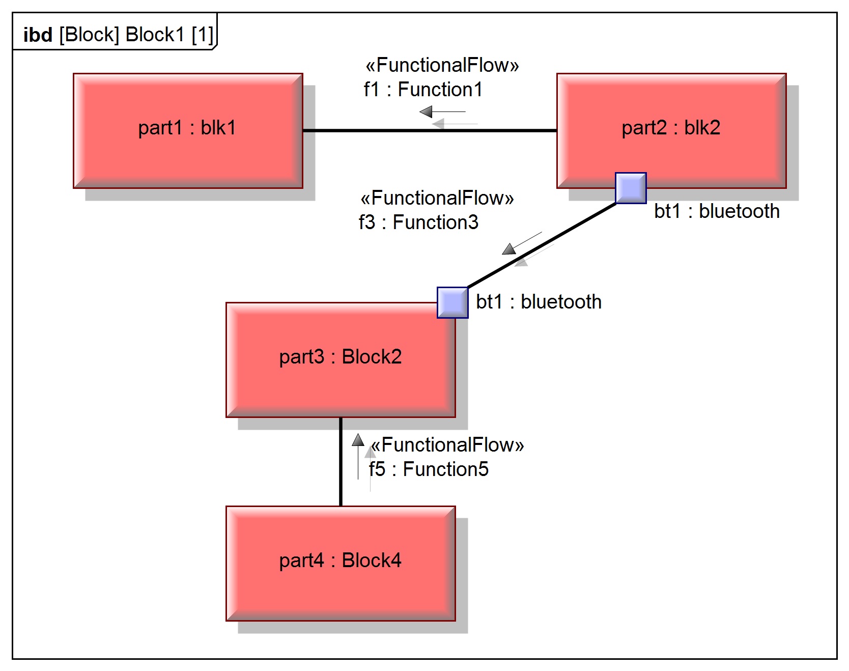
I am suggesting a slight modification of the above method of Function as Blocks in using item flows as <<functional flows>> to represent <<functions>>. In order to perform functional decomposition, we must consider a function as an item flow. We will then allocate the function to its form via an IBD, where the sending side block property (the form) sends its function to the other parts of the system. We can ask, are we allocating to parts or the types of the system, <<functions>> to types or <<functional flows>> to system blocks or parts? This aside, we can also ask: “if a particular interface breaks down, what functions does it hinder?” Because we show functions on the connecting lines between system blocks, we immediately see this relationship. Thus when examining later, it will show a relationship to the defining elements, instead of some sub-defined element.
A representative physical architecture was constructed in order to allocate the various functions across the physical system. Shown below is an Internal Block Diagram (IBD) of the physical architecture.
Item Flows stereotyped by <<Functional Flows>> and typed by the respective <<function>> block. As demonstrated in the above figure, the IBD can represent a functionality “flowing” through the physical system. The ability to visualize the relationship between form and function in this way is helpful. This method is not intended to displace traditional means of visualization such as allocation matrices. It is intended to compliment those means. This visualization is advantageous during the initial understanding and creation of those allocation relationships. It has also been demonstrated to aid in discussing the relationship between function and form, which, in the author’s experience, can often be difficult.
Conclusion
With any modeling to be done in any environment like SysML or UML, you must start with the questions you are trying to answer. Then you will have some idea of how to model in a way to arrive at the answers you are looking for. I repeat this idea whenever I start any modeling. Without this approach, how would you ever know when you are done modeling?
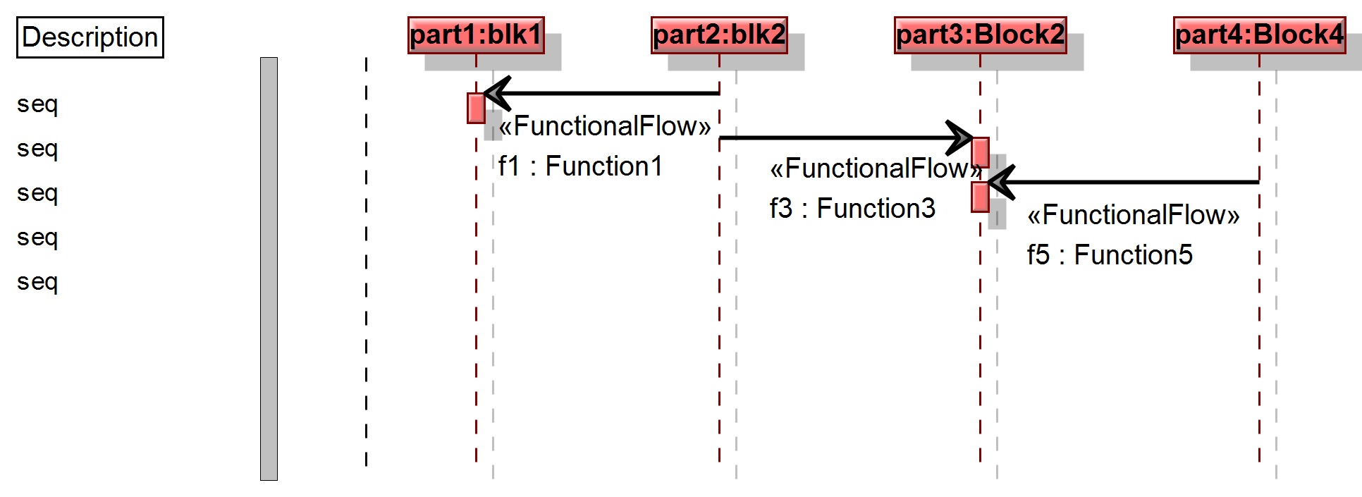
Given that I need to know from my system if a particular interface (for example Bluetooth, WiFi, or Wi-Max) breaks down, what functions are hindered from my system, this approach of using functions as blocks and using those blocks as the types of item flows, allows you to get to the answer. I would be remiss in not acknowledging that Michael’s techniques of operations as function would allow me to draw an interaction diagram, and perform similar Q&A practices.
I have spent a considerable amount of time in modeling functions over the years, and I prefer this methodology because the IBD view shows at a high level what parts of the system are sending functionality to which other parts of the system, in one view.