SysML 2 now includes capabilities for modeling basic geometry, which is crucial for the conceptual design phase of complex systems. This feature, demonstrated through a FreeCAD integration proof-of-concept, allows for the definition of enveloping shapes, coordinate frames, and transformations. It enables quick visualization, early-phase analysis of properties like center of mass, and automated checks for spatial interference, aiming to streamline concurrent engineering and ensure consistency between the systems model and specialized CAD tools.
Key Points
- Concurrent engineering, supported by a shared model, significantly reduced conceptual design study time from 6–9 months to 4–6 weeks.
- Basic geometry in systems modeling is essential for quick visualization, defining physical architecture, and sharing geometric properties (like center of mass) between disciplines.
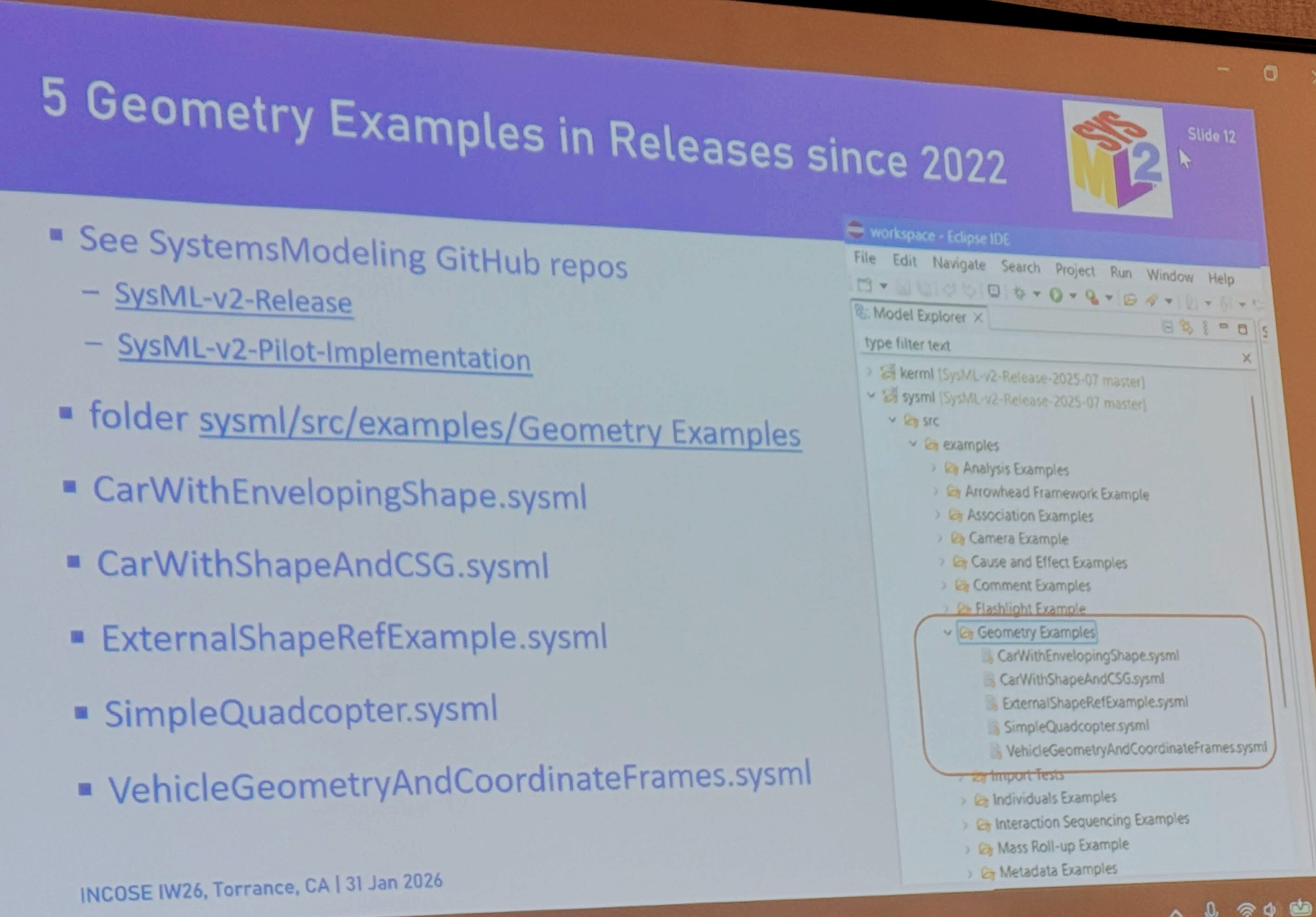
- SysML 2 supports basic geometry through its standard library, including primitive shapes (box, cylinder, sphere) and Constructive Solid Geometry (CSG) for unions, intersections, and differences.
- Models support nested coordinate frames that can be translated and rotated, with transformations integrated with the quantities and units model.
- The geometry modeling capabilities are designed to be one-to-one mappable with the STEP standard for interoperability with CAD tools.
- The Region Connection Calculus (RCC-8) is adopted to logically compute and define spatial relationships between volumes, such as checking for overlaps.
- A proof-of-concept using FreeCAD demonstrates bidirectional communication between a CAD model and the SysML 2 representation.
- The system can model kinematics by parameterizing coordinate transformations, allowing for the simulation of rigid body dynamics like deploying solar arrays.
- Continuous interface control checks can be automated to detect if any solid volumes are intersecting, preventing design constraint violations.
- A key future goal is to synchronize the assembly tree in the CAD model with the product structure in SysML 2, which is critical for team-wide consistency.
Highlights
“The first step is to get it correct and robust, and then work on the user friendliness.”
“If you don’t do it from the start, then it will never happen basically in the project.”
Topics
1. Introduction to Concurrent Design and SysML 2
- The speaker introduced his background with the European Space Agency, highlighting a sophisticated concurrent design facility that reduced conceptual study time from months to weeks by using a shared, synchronized model. The current work involves rehosting this system on SysML 2, and this presentation is a follow-up on the development of its geometric modeling API.
- Concurrent design facility reduced conceptual design time from 6–9 months to 4–6 weeks.
- The facility uses a single, shared model with a hub-and-spokes architecture connecting various engineering tools, synchronizing twice a minute.
- The speaker is now working on rehosting the entire system on SysML 2.
2. The Need for Basic Geometry in Systems Modeling
Basic geometry is crucial in systems modeling not for detailed CAD, but for defining basic enveloping shapes, their placement, and orientation. This provides quick visualization, a comprehensive view of the physical architecture, and a single authoritative source for shared geometric properties like center of mass and moments of inertia, which is essential for coordination among interdisciplinary teams.
- Basic geometry is used for enveloping shapes (boxes), their size, position, and orientation.
- It offers quick visualization and helps clarify responsibilities for different parts of the physical system.
- The systems model becomes the authoritative source of truth for shared geometric properties like center of gravity and moments of inertia.
3. SysML 2’s Geometric Modeling Capabilities
SysML 2 supports basic geometry through its kernel and standard libraries. It provides primitive mathematical shapes (box, sphere, cone) and Constructive Solid Geometry (CSG) operators (union, intersection, difference) to build more complex shapes. The system also supports nested coordinate frames and transformations, which are fully integrated with the quantities and units model, and is designed for easy mapping to the STEP standard for CAD interoperability.
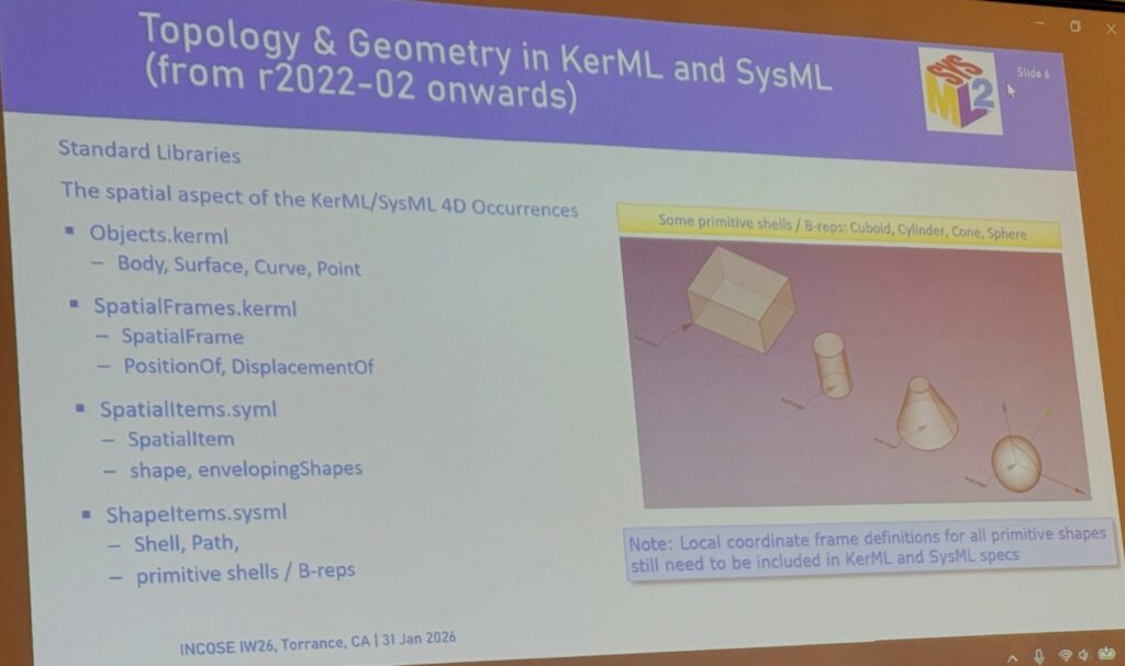
- SysML 2 standard library provides shapes and spatial items to define and manage geometry.
- It supports primitive shells and solids like boxes, cylinders, cones, and spheres.
- Constructive Solid Geometry (CSG) allows for creating complex shapes through unions, intersections, and differences.
- The model supports coordinate frames and transformations that are integrated with quantities and units.
4. Spatial Relationships and Interference Checking
- The framework uses Region Connection Calculus (RCC-8), a logic based on set theory, to define eight possible spatial relationships between volumes (e.g., disjoint, touching, partial overlap). This logic, combined with CSG, enables automated checks to ensure that no two objects improperly occupy the same space, which is a critical aspect of interface control.
- The Region Connection Calculus (RCC-8) is a logical framework used to compute relationships between two volumes.
- There are eight possible relationships, such as “disjoint,” “externally connected,” and “partial overlap.”
- This allows for systematic checks, like ensuring a sensor’s field of view is not obstructed or that two parts do not collide.
5. Proof-of-Concept Demo with FreeCAD
A proof-of-concept demonstrated bidirectional data exchange between a SysML 2 model and the open-source CAD tool FreeCAD. The demo showcased a spacecraft model with deployable solar arrays and a radiator, where parameters like deployment angles could be controlled from a spreadsheet to update the 3D model. It also showed how keep-out volumes could be defined and interference checks could be performed to identify design conflicts, such as a rotating radiator intersecting with an instrument’s field of view.
- A bidirectional link between SysML 2 and FreeCAD was created as a proof of concept.
- The demo included a spacecraft model with a deployable radiator, where the deployment angle was a controllable parameter.
- It showed how to define keep-out volumes and perform boolean intersection checks to detect spatial conflicts automatically.
6. Future Work and Remaining Challenges
Future work focuses on finalizing the API connection using OpenMB Flexo, improving usability, and resolving specification details, such as clearly defining the local coordinate frames for primitive shapes. A major priority is to perfect the bidirectional synchronization between the SysML product structure and the CAD assembly tree, as this alignment is crucial for project success and effective collaboration across all engineering disciplines.
- Key future work includes finishing the API connection and improving the usability of the geometry capabilities.
- An important task is to ensure the assembly tree in the CAD model synchronizes bidirectionally with the product structure in SysML 2.
- The specification needs refinement, such as clearly defining local coordinate frames for primitive shapes.
Suggestions
- The first step is to get it correct and robust, and then work on the user friendliness.
- If you don’t do the synchronization of the assembly tree with the product structure from the start, then it will never happen basically in the project.
AI Suggestions
- The core of this lesson is understanding “Basic Geometric Modeling in SysML.” It’s recommended to start with modeling a simple assembly with moving parts to grasp “Basic Geometric Modeling in SysML” through defining shapes, coordinate frames, and parametric transformations.
- Core content of “Basic Geometric Modeling in SysML”: The practice involves using a systems modeling language to define the basic shapes (e.g., boxes, cylinders), positions, and orientations of physical components. It includes creating nested coordinate frames to represent assemblies and using parameters to control transformations (e.g., rotation, translation) to model kinematic behavior and check for spatial interference.
- Extracurricular Resources:
- [Introduction to SysML v2: An official OMG resource page with links to the specification and pilot implementations.: https://www.omg.org/sysml/]
- [FreeCAD Official Website: The open-source parametric 3D modeler used in the lecture’s proof-of-concept, which you can download and experiment with.: https://www.freecad.org/]
- [Constructive Solid Geometry (CSG) on Wikipedia: An article explaining the fundamental concepts of CSG, which is a core capability mentioned for building complex shapes in SysML.: https://en.wikipedia.org/wiki/Constructive_solid_geometry]