 I have noticed an increasing trend where more and more companies and government agencies are required by contract to perform Failure Modes Effects Analysis (FMEA). For example, the Food and Drug Administration (FDA) has mandated that FMEAs must be done for any product that is put out on the market. In general, every company that is producing any product should have a design and a FMEA. That same design should trace to requirements, define any hazards that may exist, and should be able to demonstrate the failure modes. Similarly, many original equipment manufacturers (OEMs) are following suit in requiring FMEAs in the production of parts and in the making of devices. For this reason, medical, aerospace, and automotive companies alike, all understand the need to generate FMEA tables and forms in order to prove acceptability in the marketplace. Traditionally FMEAs are captured in a spreadsheet format, either by tools like Windchill Quality Solutions, ReliaSoft’s Xfmea, or simply captured in Excel. Because my focus is modeling systems designs, I am in the process of developing a modeling technique which can enable systems engineers to easily access, create, trace, model the information they need.
How is Risk Assessment Different Than FMEA?
Risk assessment has to do with looking at the product itself and assessing it, or quantifying it, in order to determine the likelihood of a certain risk. FMEA describes when you are doing analysis against your actual product, or the end thing. It is the process of identifying the failure mode of the system, analyzing it, and determining what to do when it happens. It asks the question, “what do I have to mitigate or resolve the failure and how am I going to do that?” FMEA, as a whole, should include the design (dFMEA), the instructions for use (uFMEA), and the manufacturing process (pFMEA). All of these can have failure modes, and they can all have effects. In order to figure out how to resolve these before getting to the end, analysis must be done.
Why Model Your FMEAs
FMEAs can be modeled in such a way to be tied to your systems. By doing modeling, the review process will be much easier because everything will be traced to what is necessary. As such, the model can be used during the review process and generate any answers that the reviewer may ask about the product. After the model is generated, you can then do traceability to your systems, subsystems, and requirements. You can also list your failure modes and the estimated effects. In addition to structural design, you can draw a process in an activity diagram, and then generate those linked items into the traditional spreadsheet format, or tool of choice.
How to Model Your FMEAs – Using SysML
Most FMEAs have been done in a spreadsheet like format, showing a big list of things including the risks, the mitigation, the analysis, and a whole host of other items. The following diagrams demonstrate how you can, starting with your design, apply our FMEA profile to your model, import or type your failure modes and trace them to your design, functions, or interfaces, behavior, any Meta Object Format (MOF level) all the way down to the attributes of a particular system.
A Typical SysML Design With Physical Interfaces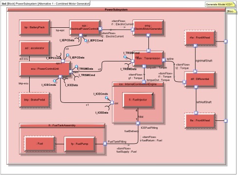 Figure 1. Internal Block Definition Diagram [Physical connections]
Using SysML you can model anything from the real world. You can model down to the wire on a circuit board and highlight the failure due to EMF issues etc.
Acquire an FMEA profile (shown below) from MBSE Solutions. Using this profile, you can trace to your design or functions to create design FMEA (dFMEA). You can identify failures on any modeling item in the model using this profile. Creating a trace relationship sets up the data relationship necessary to generate information into any FMEA tool or FMEA spreadsheet.
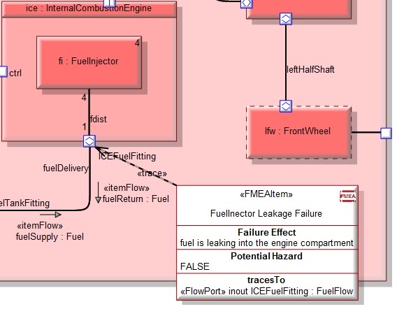 Figure 2. dFMEA Diagram Example focused on the lower right of Figure 1 above.
You can also create a uFMEA (usage FMEA) to analyze how the user will use the system and the potential failure modes that may come of that, as shown below.
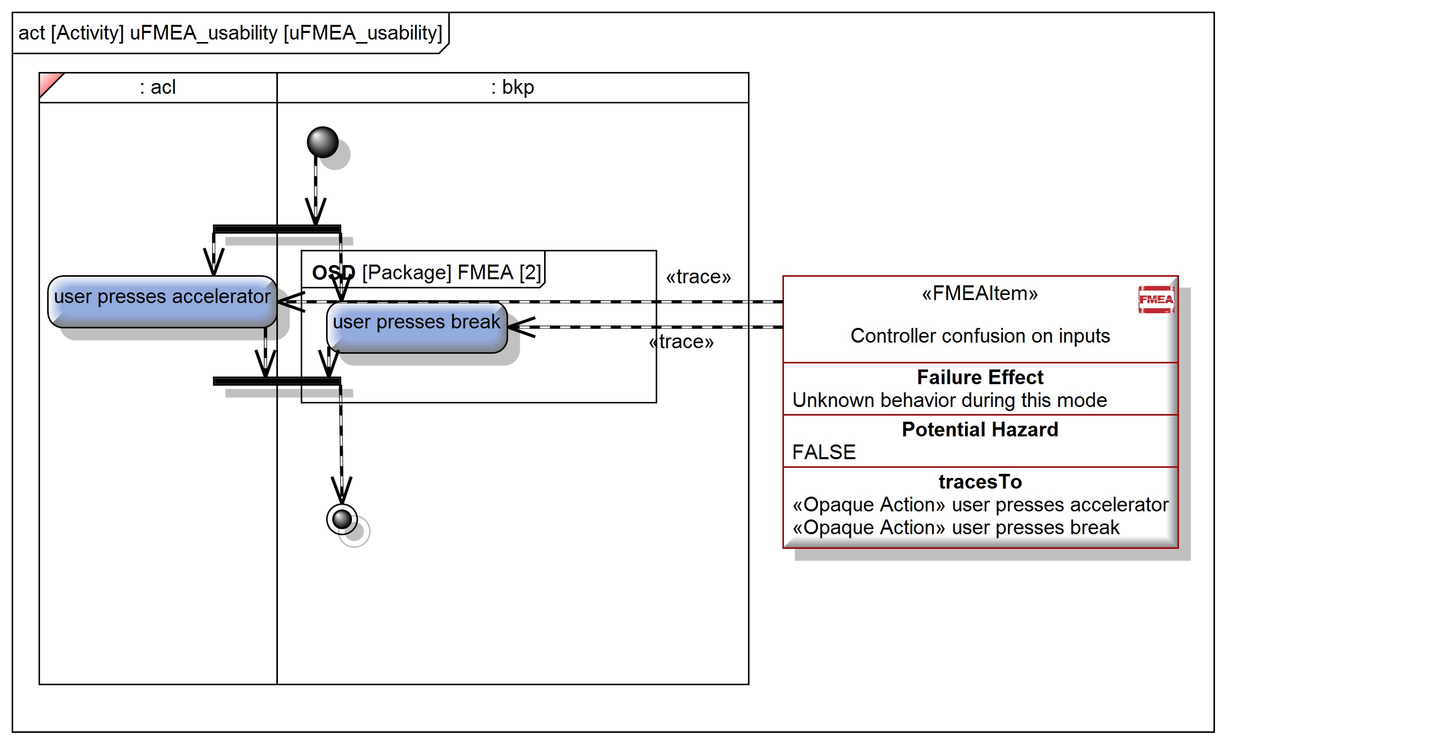
Figure 3. uFMEA Diagram Example
NOTE: The best way to show usability in modeling is to do a “use case” and an “activity diagram” to describe flow. Swim-lanes will be the systems that the user interacts with for that failure. This information can be traced to the systems it may affect as well.
pFMEA is defining the process of the system being built and identifying potential failure modes during construction. This is best described as an activity diagram where each swim-lane will be the person/equipment involved in doing that process step. The effects detection will be directly identified in the activity step.
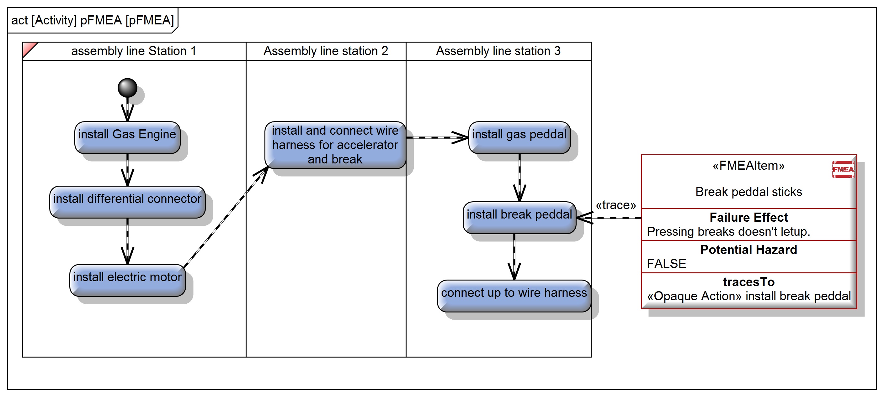
Failure during installation process.
Each FMEA Item will generate a row in the FMEA table. Tied to any modeling (MOF level) attribute that you need to identify as a failure in the system. All values are generated into FMEA tools of your choosing or spreadsheet formats.
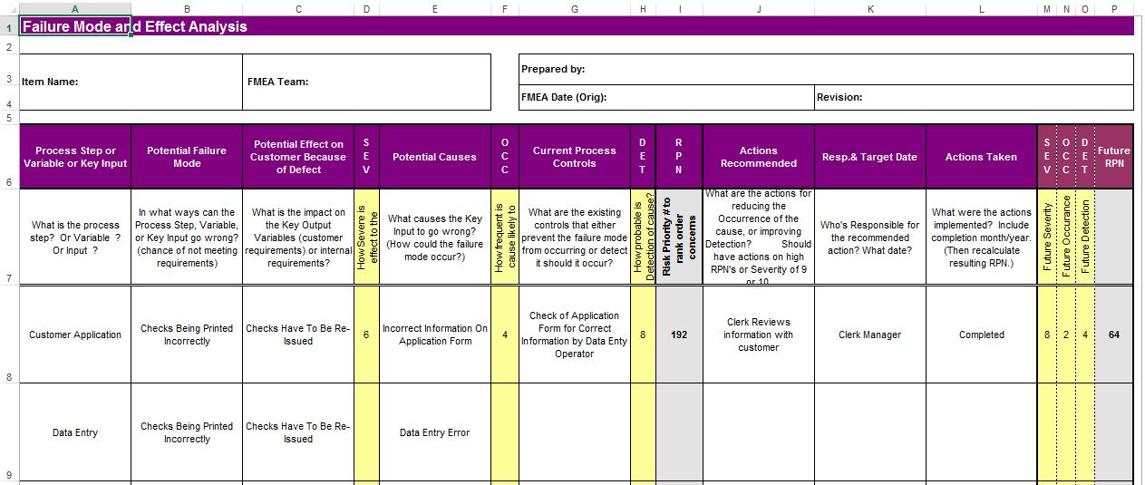 Figure 5. A typical FMEA Spreadsheet Example